Portable solar v1
Beginnings§
As I need power for my portable rainbows, and I think I over-discharged the lithium battery I used over New Years’ (oops!)…
I got a new portable 120w solar panel and a used 85Ah flooded lead acid battery, gonna make a 5v usb charging station to bring to Kiwiburn in 1.5 weeks! I’m keen for this to be my first step into learning about practical solar and battery power, even if I live day-to-day on-grid.
Here’s me testing what I have in the sun this morning:

Worked with Piet last night at Art~Hack to understand how to control a battery’s discharge.
Then Ben informed us that solar charge controllers already do this, they will shut off the “load” output when the battery is low.
If so, making a 5v usb charging station should be really easy, just get a step down buck converter and convert 12v to 5v, then fan out this power to many usb connectors.
Stretch goal will be to make a nice display of the current power level, with maybe some playful messages as the power charges or discharges.
🌈 ☀
Documentation§
Source: ahdinosaur/solarmonk
Components§
Solar panel (with built-in charge controller)§
120w maxray folding solar panel
- Max Power: 120W
- Maximum Power Tolerance: ±3%
- Open-Circuit Voltage/Voc(V): 17.5V
- Short-Circuit Current/lsc(A): 9.42
- Max Power Voltage/Vmp(V): 14.0
- Max Power Current/lmp(A): 8.57
- Power Spectications at STC: 1000w/㎡,AM1.5,CELL25℃
- Max System Voltage(V) 1000
- Max Over Current Protecting Rating(A): 15
- Weight: 12.6kg
Battery§
12v - 85Ah deep cycle flooded lead acid battery
voltage must not drop below 11v
fully charged is 12.6v to 12.8v
| State of Charge (approx.) | 12 Volt Battery | Volts per Cell |
|---|---|---|
| 100% | 12.70 | 2.12 |
| 90% | 12.50 | 2.08 |
| 80% | 12.42 | 2.07 |
| 70% | 12.32 | 2.05 |
| 60% | 12.20 | 2.03 |
| 50% | 12.06 | 2.01 |
| 40% | 11.90 | 1.98 |
| 30% | 11.75 | 1.96 |
| 20% | 11.58 | 1.93 |
| 10% | 11.31 | 1.89 |
| 0 | 10.50 | 1.75 |
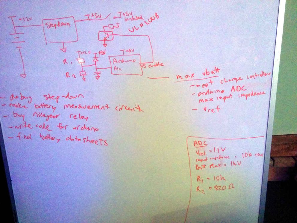
Battery charge reader§
- BTE14-04 betamcu.cn Arduino Uno R3 Compatible
- “DF Robot” LCD Keypad Shield
- R1 resistor = 10k ohms
- R2 resistor = 820 ohms
- ceramic capacitor = 100nF
- schottky diode
1 |
|
Battery discharge controller§
To ensure the battery is never over-discharged, we should cut off extra power when the battery reaches a low enough voltage.
12v to 5v step-down (buck) converter§
step down dc-dc 9A converter (constant volts or constant amps), 5~40v input & 1.5~35v out
Calculations§
Resistive divider§
To measure the battery voltage on the microcontroller, we divide the voltage using resistors:
Given
- adc input impedence = 10k ohms
- adc reference voltage = 1.1V
- max battery voltage = 14V + wiggle room = ~15V
So R1 = adc input impedence = 10k ohms
(want to be as high as possible to reduce current)
Calculate
1 | R2 = R1 * (1 / ((Vin / Vout) - 1)) |
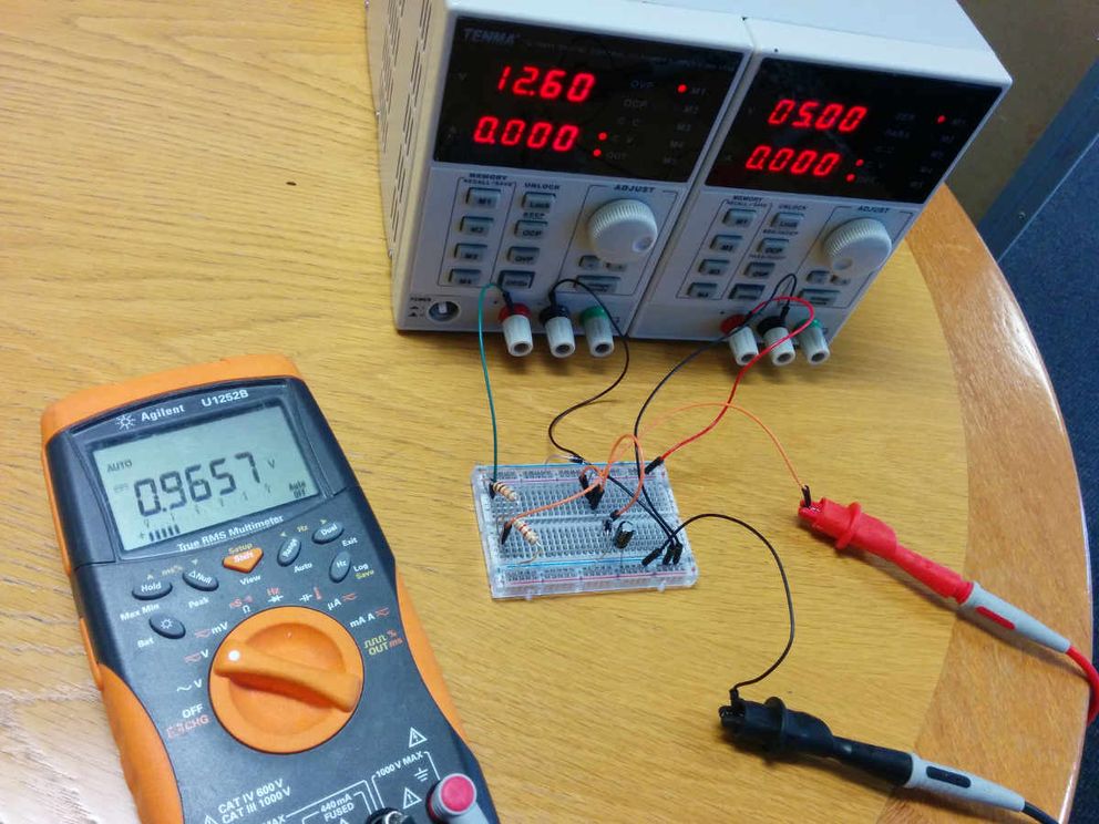
Battery charge reading§
Piet let me borrow his power supply and multimeter so I could make sense of this.
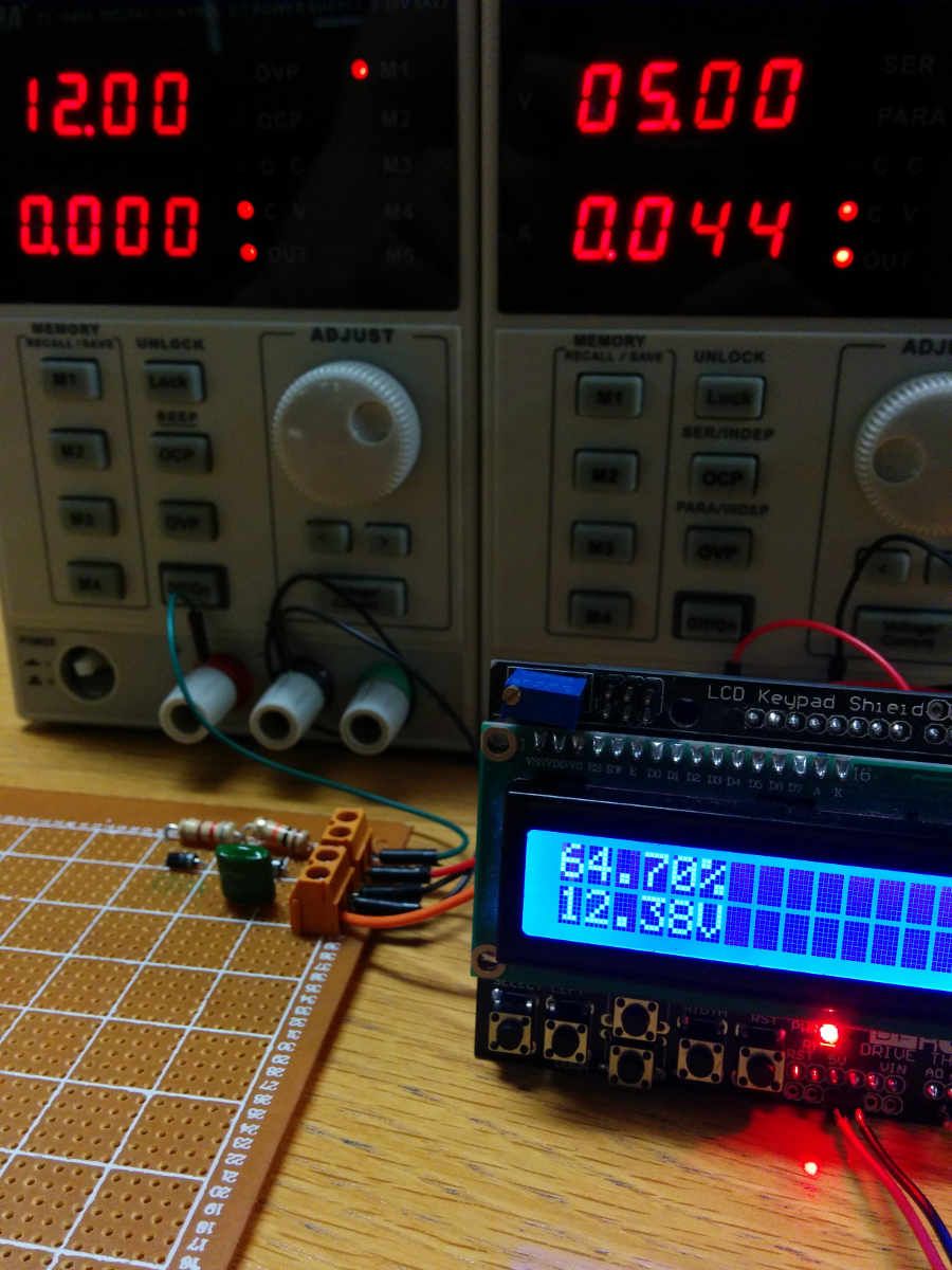
Got it working on a breadboard, then soldered to a protoboard. Threw up some code to run on the Arduino with the screen.
There’s a problem where the voltage being read by the Arduino is quite a bit off, I hope at least it’s consistent so I can calibrate against it. I learned that this might could be improved by investing in a good reference voltage, oh well for meow.
I also learned that batteries have wildly different voltages when charging, at rest, and discharging. In the worst case i’ll be conservative, bring a multimeter to the festival, and manually ensure that we never discharge too much power.
Next up will be to put all the bits and bobs in an enclosure and at least get the 12v to 5v conversion working reliably, with 2.1mm barrel connector and usb outputs.
ready or not, here I come!§
Spent the last few days detached from reality flowing like hot solder.
Now have:
- 1x “solarmonk” controller
- input is 12v with xt60 male connector
- outputs
- 5x 5v with 2.1mm dc female mount
- 2x 5v usb female connector
- 1x “aburndance” controller
- outputs for APA102 leds
- 5x 7.5A 2.1mm male-to-male cables (of varying lengths from 2m to 15m) to re-inject power to the led strips
- 3x 25A xt60 male-to-female extensions (1x 8m and 2x 4m ish)
(Apologies for using human gender terms to describe hardware connectors, is there a better alternative?)
At one point it had an arduino with a display showing the connected battery voltage and current amperage draw, but last night when I should have been sleeping, I connected everything up and it didn’t work. Without a load, everything checked out on the multimeter great, but then with a working load (the led strips), it buggered out. Since the buck converter does both constant voltage and constant current, I thought maybe I had set the constant current the wrong way. so I set it all the way to one side. But it still didn’t work, so I checked the voltage: 3v. When it was 5v without a load.
Then I made a terrible mistake, I increased the voltage, eventually to the point where I burned the led strips and the arduino. I stopped being silly and went to sleep. Today I checked everything with a clear head, luckily the most important part, the buck converter, was not affected by the damage. With some debugging, I realized the voltage had dropped because the constant current was set to the lowest setting. Now I think everything is working for real at 5v?
Here’s a picture so I can say, at some point something worked:
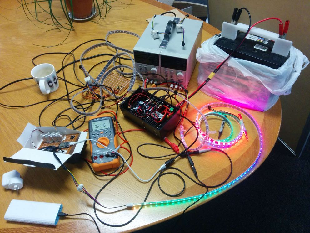
Remains to be seen if anything will work on the paddock. ☀🔋🌈
I’ve learned so much! I’m learning how to do hardware in a way that is reliable and so doesn’t suck when you want to play with software.