First look at Blinksy
Oops I went down a rabbit hole and discovered this: Blinksy 🟥🟩🟦
A Rust no-std no-alloc LED control library for spatial layouts
What’s in this post?§
Backstory§
I wanted to make a LED control library that could do the following:
- Like FastLED, support all the most common LED pixel chipsets such as WS2812, APA102, and more.
- Like WLED, have a library of beautiful visual patterns.
- Unlike anything before, support not just strips and grids, but any 1D, 2D, or even 3D spatial layout.
- By using Rust, have an modern and delightful developer experience.
I had some previous learnings with LED pixels:
And learnings with advanced generics for no-std no-alloc embedded Rust.
Announcing: Blinksy§
Blinksy is a new LED control library for 1D, 2D, and soon 3D spatial layouts*.
* 3D layouts are coming soon, because I want an LED cube like this with native 3D animations!
Examples§
Desktop Simulation: 2D Grid with Noise Pattern§
Click to see code
1 | use blinksy::{ |
Embedded: 2D APA102 Grid with Noise Pattern§
Click to see code
1 |
|
Embedded: 1D WS2812 Strip with Rainbow Pattern§
Click to see code
1 |
|
How Blinksy works§
- Define your LED
layoutin 1D, 2D, or soon 3D space - Create your visual
pattern(effect), or choose from our built-inpatternslibrary- The pattern will compute colors for each LED based on its position
- Setup a
driverto send each frame of colors to your LEDs, using our built-indriverslibrary.
To best support embedded devices, this is possible without the Rust standard library (no-std) and without any memory allocations to the heap (no-alloc).
Define your LED layout§
A layout defines the physical or logical positions of the LEDs in your setup, as arrangements in 1D, 2D, and 3D space.
To define a layout, we must define a struct that implement either the Layout1d, Layout2d, or soon Layout3d traits. To make this easy, we use either the layout1d, layout2d, or soon layout3d macro, respectively. These traits provide a PIXEL_COUNT constant, which is the number of LEDs, and a .points() method, which maps each LED pixel into a 1D, 2D, or 3D space between -1.0 and 1.0.
(For any Rust beginners: A struct is a definition of a type of object, like a class in other languages. A trait is a definition of an abstract behavior that an object might implement, like an interface in other languages. A macro is code that generates code, like a function that you call during compilation to return code, rather than call during runtime to return a value.)
1D layouts§
For a 1D layout, this is very simple, as a 1D shape only has a length.
Here is a layout for an LED strip with 60 pixels.
1 | layout1d!(Layout, 60); |
For our 1D space, the first LED pixel will be at -1.0 and the last LED pixel will be at 1.0.

2D layouts§
For a 2D layout, you need to define your 2D shapes: points, lines, grids, arcs, etc.
For our 2D space, we can think of:
(-1.0, -1.0)as the bottom left(1.0, -1.0)as the bottom right(-1.0, 1.0)as the top left(1.0, 1.0)as the top right
Here is a layout for a basic 16x16 LED grid panel to span our 2D space:
1 | layout2d!( |

Create your visual pattern§
A pattern, most similar to a WLED effect, generates colors for LEDs based on time and position.
We define this as a struct that implements the Pattern trait.
1 | /// # Type Parameters |
While there is one Pattern trait, it may be implemented for any dimension, using a dimension marker: Dim1d, Dim2d, or soon Dim3d. The dimension marker will then constrain the Layout generic provided, to implement either Layout1d, Layout2d, or soon Layout3d, respectively.
On initialization, the pattern is given configuration parameters. On every update, the pattern is given the current time in milliseconds, and must return an iterator that provides a color for every LED in the layout.
The color types in Blinksy are inspired by the palette crate, where they implement FromColor and IntoColor. Like FastLED we have Hsv (which uses FastLED’s rainbow hues), or for a more modern color space we have Okhsv.
To use a pattern, we can either choose from the built-in library or create our own.
We have two visual patterns to start, each implementing Pattern for 1D, 2D, and soon 3D.
Or feel free to make your own. Better yet, help contribute to our library!
Setup your LED driver§
Now for the final step.
The driver is what tells the LED hardware how to be the colors you want.
To define a driver, we must implement the Driver trait:
1 | pub trait Driver { |
The driver says what type of error it might return and what type of color it wants to receive.
When you write to a driver, you provide an iterator of colors (in your own color type), plus a global brightness and color correction.
What colors do an LED understand?§
The LED driver will be given colors from the visual pattern, then convert them into a new color type more suitable to what the LED hardware understands.
LEDs are generally 3 smaller LEDs, red + green + blue, each controlled via pulse-width modulation (PWM). If you tell an LED to be 100% bright, it will be on for 100% of the time (a 100% duty cycle). If you tell an LED to be 50% bright, it will be on for 50% of the time (a 50% duty cycle). And so on. Our eyes don’t notice the flicker on and off.

Therefore, we use LinearSrgb when thinking about LEDs, since linear color values correspond to the luminous intensity of light, i.e. how many photons should be emitted. However, what we actually perceive in a linear change in photons is not linear. For our evolutionary survival, we are much more sensitive to changes in dim light than we are to changes in bright light. If you double the amount of photons, we don’t see double the brightness.
This mismatch between physics and perception is why the “RGB” you think you know is actually gamma-encoded sRGB. sRGB allows us to think in terms of perception, where double the red value means double the perceived brightness of red. Then for LEDs, we convert the gamma-encoded sRGB to linear, to use as a gamma-corrected duty cycle.

By the way, if you start mixing RGB’s, make sure to do so in the linear space.
So anyways, why red, green, and blue? These correspond to the 3 light receptors in our eyes. What we perceive as color is some combination of these receptors being trigged. Our brain doesn’t know the difference between seeing the yellow wavelength as seeing a combination of the green and red wavelengths at the same time. We don’t see color as we might think. There’s no such wavelength for purple (not to be confused with violet), yet our brain makes up a color that we see.

There’s more. We say RGB, but what red, what green, what blue? To solve this, the sRGB color space defines an exact red, an exact green, an exact blue. But is the color in our color system the same as the color being output by our LEDs?
I could go on about colors, there’s more to say, more future work to be done in Blinksy, but that’s enough for now.
What protocols do an LED understand?§
To make implementing Driver easier for the various LED chipsets, we have generic support for the two main types of LED protocols:
Clocked LEDs (SPI)§
A clocked protocol is based on SPI, where chipsets have a data line and a clock line.
For every bit we want to send from the controller to the LEDs:
- First the controller sets the data line (MOSI) to HIGH for a 1 or LOW for a 0.
- Then the controller “ticks” the clock line (SCLK), by going from LOW to HIGH.
- On the rising edge of the clock line, the LED will read the data line.
- Halfway through the clock cycle, the controller will reset the clock line to LOW.

To define a clocked LED chipset, you define the ClockedLed trait.
Clockless LEDs§
A clockless protocol is based on specific timing periods, where chipsets have only a single data line.
Without a clock, the protocol depends on specific timings to represent each bit.
For example with WS2812B LEDs, to represent a 0 bit the data line must be HIGH for 0.4 microseconds, then LOW for 0.85 microseconds. These timings must be accurate to within 150 nanoseconds. That’s tiny!

With these timings in mind, we can send some bits without a clock.

To define a clockless LED chipset, you define the ClocklessLed trait.
Protocol drivers§
For each generic LED protocol type, we have specific protocol drivers for those types of LEDs:
- By bit-banging over GPIO pins, using a delay timer.
- Or by using an SPI peripheral.
For clockless protocols on ESP devices, we can also use the RMT peripheral.
(Note: I have yet to drive clockless LEDs using an SPI peripheral. For now I’m happy with my ESP32’s RMT peripheral. If you want this, maybe you can help?)
What LEDs can we talk to?§
At the moment, Blinksy supports:
- APA102 LEDs, aka DotStar
- WS2812 LEDs, aka NeoPixel
With the above protocol abstractions, adding a new LED chipset is as easy as implementing ClockedLed or ClocklessLed.
By the way, props to smart-leds for paving the way on addressable LED drivers in Rust.
Get started§
Put everything together§
Okay, now that we’ve learned about layout, a pattern, and driver – let’s put them together.
We use a ControlBuilder to build a Control.
For 1D:
1 | let mut control = ControlBuilder::new_1d() |
For 2D:
1 | let mut control = ControlBuilder::new_2d() |
ControlBuilder means we don’t have to think about all generic types involved in a Control, we can add each part one at a time.
From here we can set a global brightness or color correction.
Then we run our main loop, calling .tick() with the current time in milliseconds.
1 | loop { |
Get running on a microcontroller§
While you can plug LEDs directly into microcontroller pins, I do recommend using an LED controller that does things properly.
I found a decent LED controller available on AliExpress: Gledopto GL-C-016WL-D.
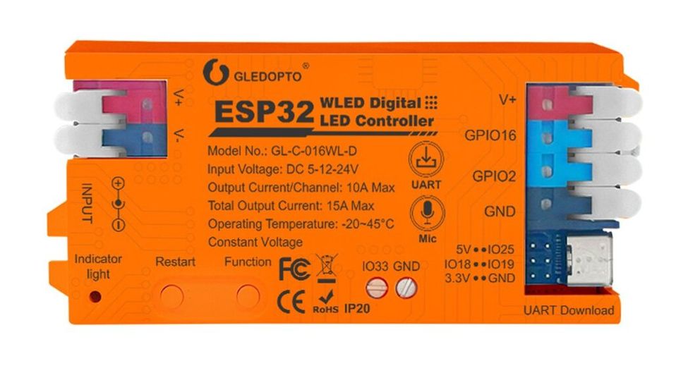
For this, I made a board support crate: gledopto.
The board support crate provides a few macros to make your life easy, such as a board! macro to setup your board, or a ws2812! macro that sets up a WS2812 driver using the specific pins for that controller.
To make even easier, I made a quickstart project template: blinksy-quickstart-gledopto
Add some LEDs§
Now you just need to add LEDs, and away you go.
If you need an LED supplier recommendation, I’ve only had success with “BTF-Lighting”. You can find them on AliExpress, Amazon, or on their own website.
If you need more help, look at QuinLED’s helpful guides.
(Note: I will later add support for QuinLED boards, since they are the best and want to support them. Unfortunately, shipping to New Zealand was too expensive, so I will receive once a friend travels over the Pacific.)
Hello LEDs§
Now, here is our hello world of LEDs:
A strip of WS2812 LEDs with a scrolling rainbow.
Click to see code
1 |
|
Or, to show some more:
A grid of APA102 LEDs with a noise function.
Click to see code
1 |
|
Simulate on your desktop§
Okay, but let’s say you just want to start now, without a microcontroller, without any LEDs.
Blinksy also has a way to simulate on your desktop: blinksy-desktop.
This provides a driver (using miniquad) and an elapsed time function.
Click to see code
1 | use blinksy::{ |
Quickstart a project§
So wanna jump in now and start your own project?
I made a quickstart project template: blinksy-quickstart-gledopto
You can even simulate on the desktop while your controller and LEDs arrive.
Thanks§
If you want to help, the best thing to do is use Blinksy for your own LED project, and share about your adventures.
If you want to say something about this post, discuss this on GitHub.
If you want to contribute code, please:
- Help port a visual pattern from FastLED or WLED to Blinksy
- Write your own visual pattern
- Help support a new LED chipset
- Help support a new LED controller
If you want to otherwise support the project, please:
- Star the project on GitHub: ahdinosaur/blinksy
- Sponsor me on GitHub: @ahdinosaur
- Subscribe to me on YouTube, to encourage me to live-code Blinksy: @Make_with_Mikey
Thanks for sharing your attention with me. Have a good one. 💜