Polyledra v1: LED tetrahedron
A light-emitting polyhedron chandelier
Source: ahdinosaur/polyledra-v1
Background§
After playing with my portable rainbows, I thought about my learning objectives for the next stage of portable rainbow exploration:
- I want to go back to the BeagleBone, but this time using Rust instead of JavaScript
- I want to get back into 3d printing for enclosures and structures
- I want to upgrade from breadboards to protoboards to custom pcb circuits, out-source soldering!
- I want to play with graphics code
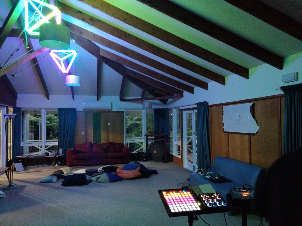
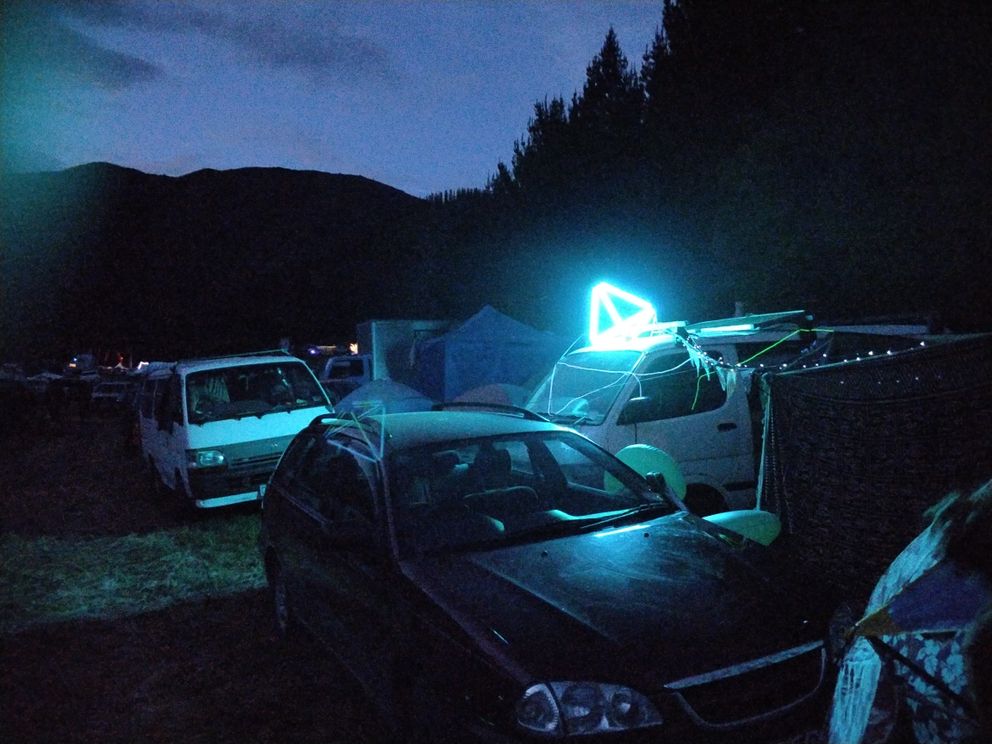
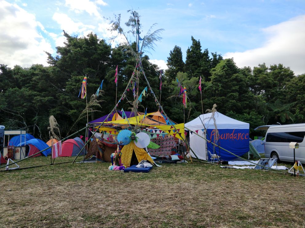
I was sitting on a hill listening to music at a gathering in the forest last weekend, when I saw a 20-sided shape hanging over a stage, with fairy lights strung around the edges. ✨
I thought “what if I did the same with leds”? 🌈
I then continued to spend the rest of the festival obsessing about the shape, leds, and rust interfaces, which led to here. 🐱
Shapes§
Design constraints§
To simplify production, we want:
- MUST HAVE uniform length edges (easy for buying led strip channels)
- COULD HAVE uniform angle patterns (easier for making 3d printed joints)
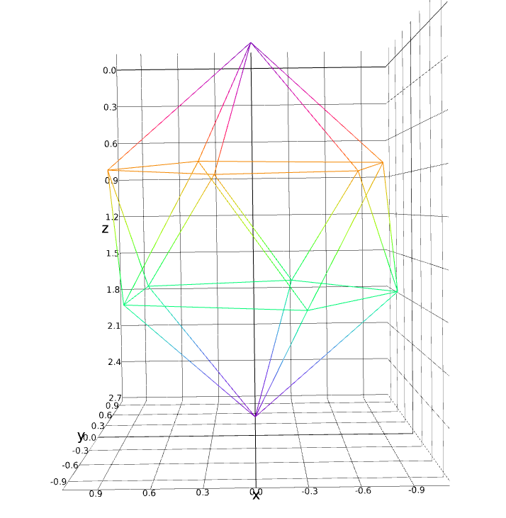
Icosahedron§
The original gansta shape from the festival!
An icosahedron is a 20-sided shape which regular angle patterns and uniform length edges.
It’s also a gyroelgonated pentagonal dipryamid (my original understanding of the shape): on the top and bottom is a pentagonal pyramid, in the middle is an pentagonal antiprism
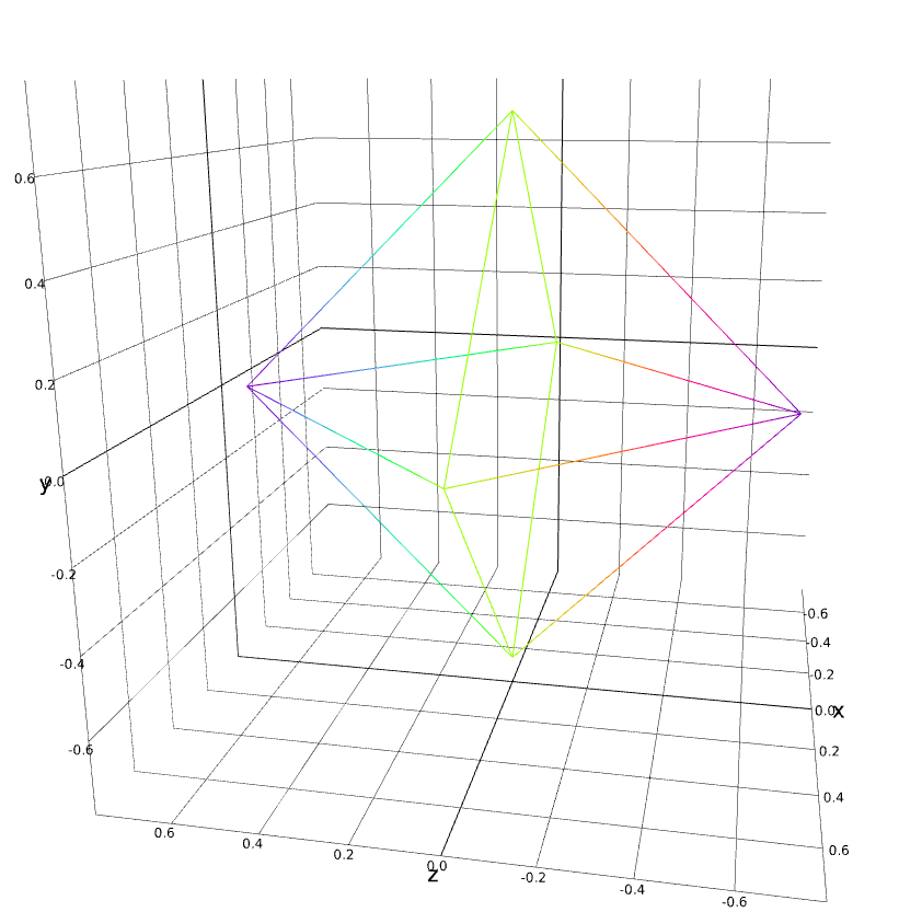
Octahedron§
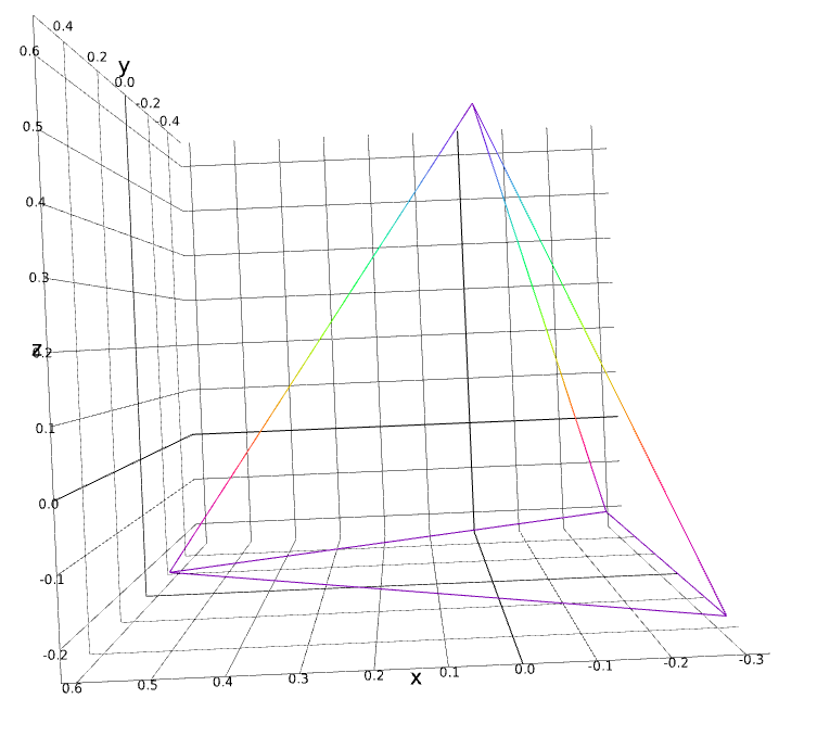
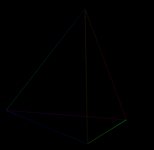
Tetrahedron§
Initial controller dive§
A Rust-y adventure§
Wow, Rust is legit!
Really enjoying how the compiler is so helpful.
Had my first fight with the borrow checker, still am on easy mode though. Had my first “spend hours writing a heap of rust code, finally compiles, and omg what it works!?”
I setup a basic multi-threaded message-passing architecture based on a conversation with Matt, thanks!
I wrote some code to derive pixel positions from an abstract shape, then on each clock tick it runs a function for each pixel that receives the position and returns the color, which are then all displayed in a 3d renderer.
I think the hard part of this project for me will be the graphics part, I find graphics code sooo confusing! At the moment was able to find a library that let me create shapes in 3d space without having to dive too deep. But I’m really keen to learn how to do proper graphics code, I forgot to mention that in my learning objectives above.
More Rust-y learnings§
Been making heaps of progress, yay learning Rust!
- in the simulator, render points instead of cubes for performance (until I do my own gl)
- play with simple animated rgb scene
- learn how non-blocking doesn’t make sense without an event loop
- create a scene manager to handle switching between many scenes
- hook up simulator window events so ‘left’ and ‘right’ switch previous and next scenes, respectively
- support hsl colors
- add simple rainbow scene
- support scenes to return generic iterators, to auto-convert colors without intermediate vecs
Shape walker§
Had a long battle with the Rust borrow checker, ended up on top! 😅
Then moved on to the puzzle of how to implement a shape walker. 🌈
From software to 3D modeling§
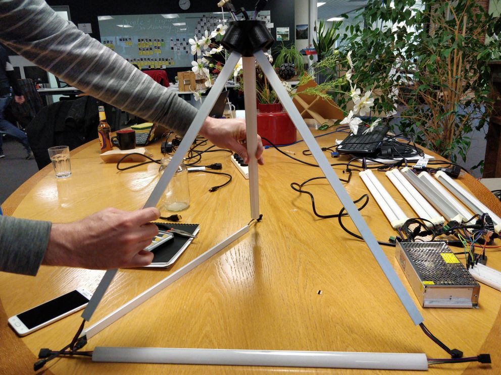
Moving from software to 3D modeling! 📐 🚥 🔆 🌈
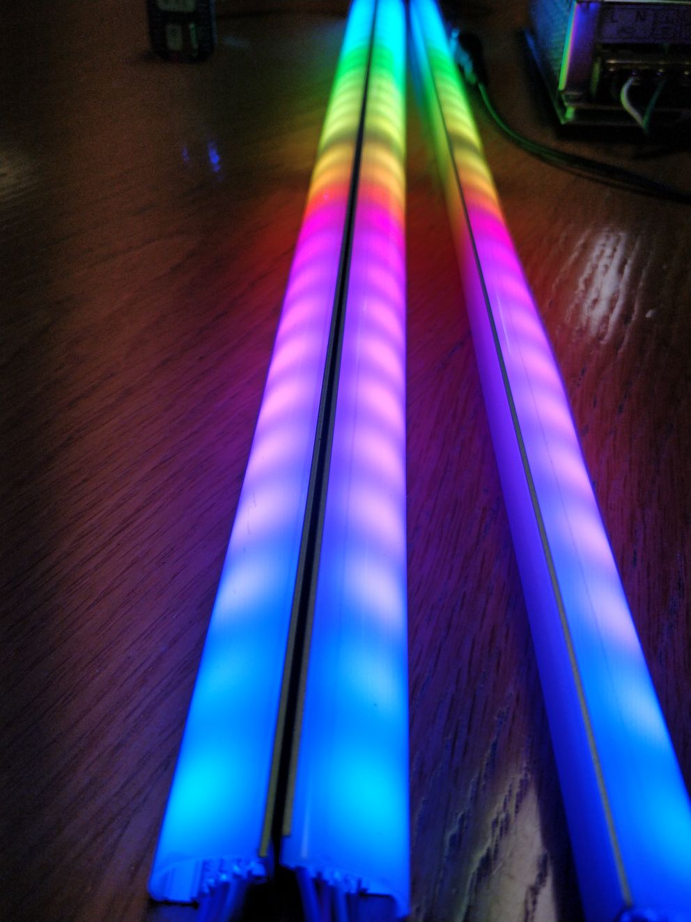
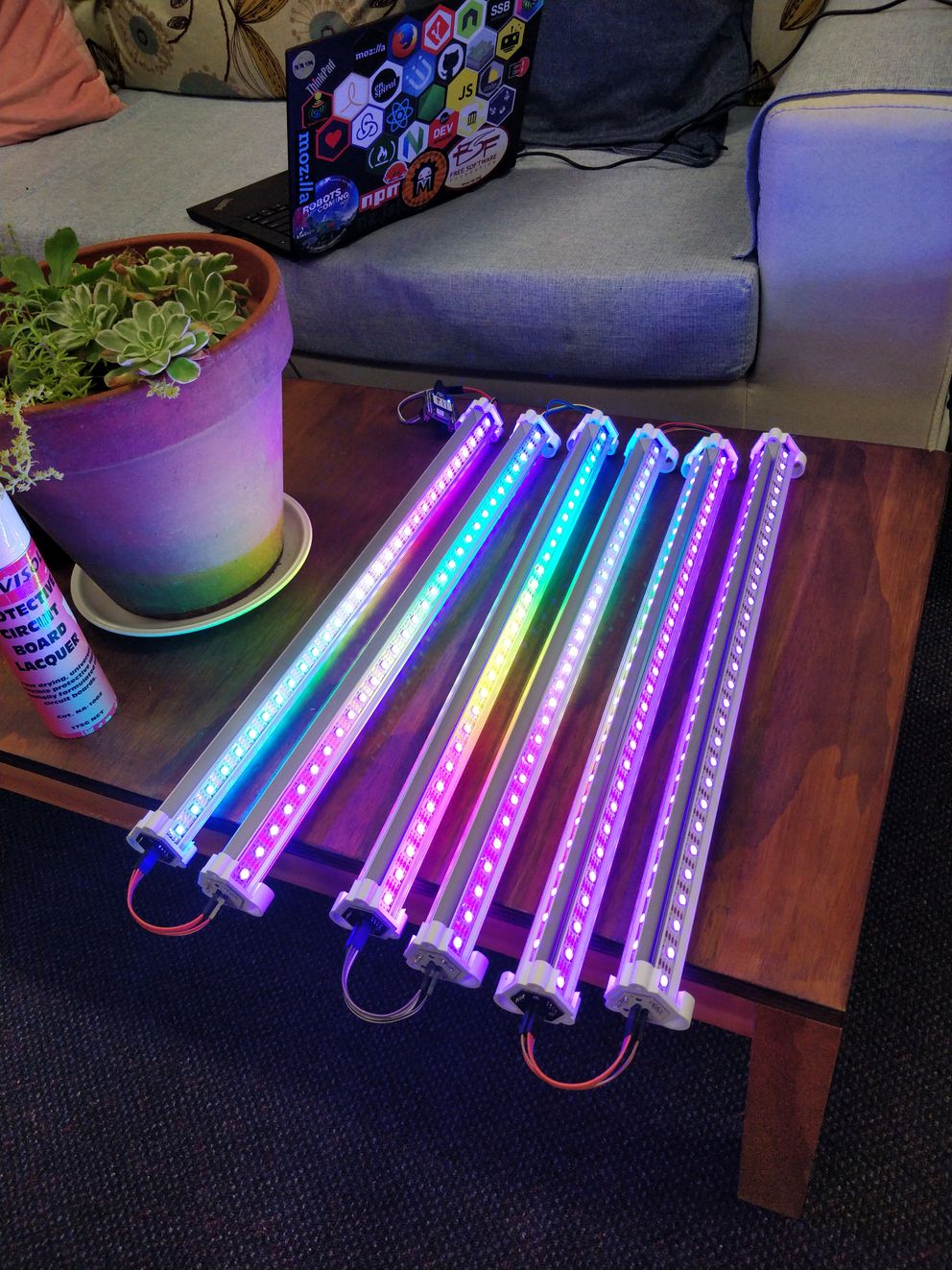
First going to build a tetrahedron, so I bought 20 aluminum led strip channels, each 0.5m long.
Here are the dimensions of each aluminum channel (except 500mm long):
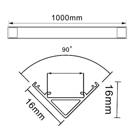
The idea is to have 3 led strip channels per edge of the tetrahedron so the edges will be lit from all angles. I had this idea before but was going to start with a single channel per edge, until I talked to my friend: she noticed that since the shapes will be regular, the best effects will come from seeing the other side of the shape through the shape!
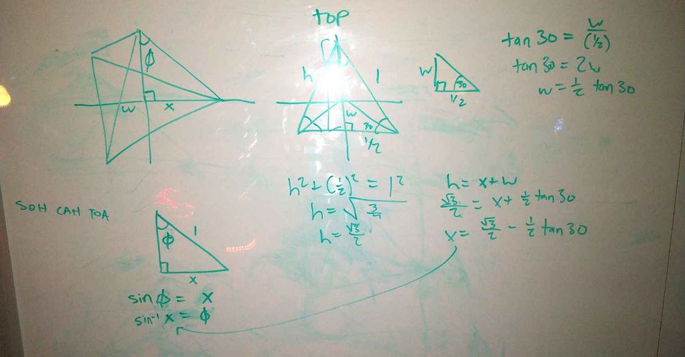
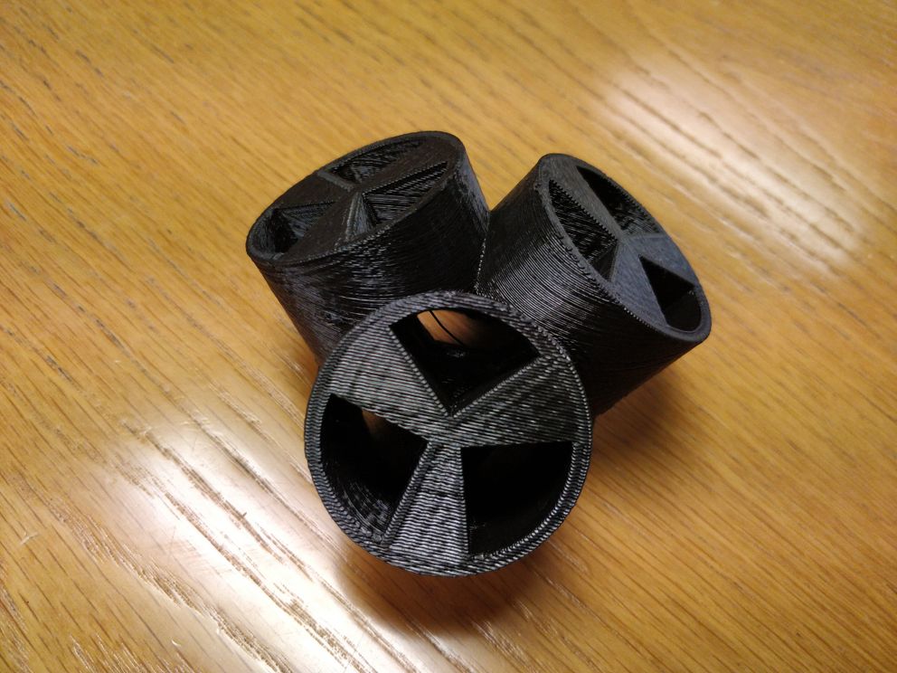
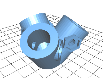
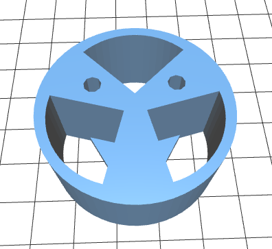
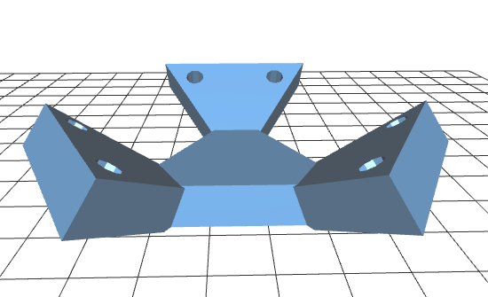
With help from Jack, I made a 3d model of the tetrahedron connectors!
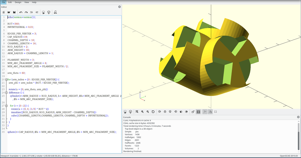
Getting ready for Winter Expo§
Mix helped me with the tetrahedron angles math, my last edge connector was so wrong 📐
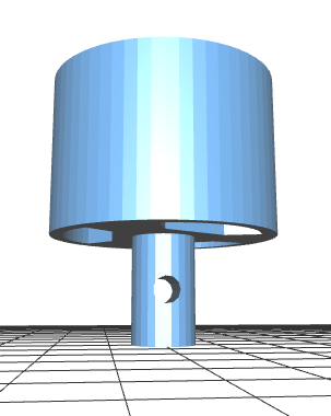
Then I completely re-structured the vertex structure, so can fit wires inside and round the back
(scad, viewable stl)
Then I made a new controller scene 🎇
(rs)
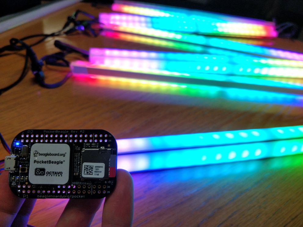
Then I got my code running on the Pocket Beagle. I love Rust where I can write code on my laptop (which doesn’t have access to an spi interface necessary to control the leds), then once I had it compile on my laptop (without ever running the code) there was only a small configuration change to make it actually work on the Pocket, yay compile-time type and borrow checking!
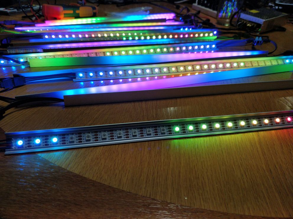
So this weekend I got the controller rust code running on the Pocket Beagle displaying on some real led hardware, with help from Piet who introduced me to japaric/cross, OMG so great.
Now I’ve prepared 15/18 led strips in aluminium channels, made an easy deploy script from my computer to the Pocket, setup the controller binary to run automatically when the Pocket starts, and fixed the code so it outputs pixel data for 3 “arms” per tetrahedron edge (3 arms per edge * 6 edges = 18 total arms).
Next up:
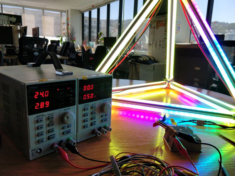
- setup power injections at regular intervals across the shape (at least 3, for 180 leds per injection)
- test the current vertex structure print actually works, tune until good
Fun learning: using rust’s --release flag led to a 10x performance increase, wow! 🌟
Keen to get this ready for the Art~Hack Wellington Winter Expo. 😅
Continued§
Yesterday fixed up the edge connector model based on feedback from my friend Jack who generously did a print some time ago. then played around with a new scene using noise functions, doesn’t look good yet but is pretty fun to play with. 🌊
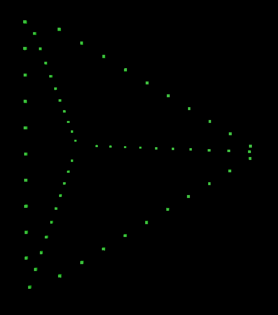
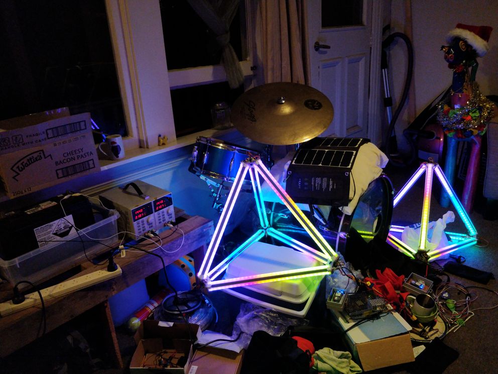
Today soldered up the power injectors (had these leftover from a previous project, they connect perfectly here!) and powered up all the leds, but turns out I had an off-by-one error! Notice the center point is no longer in the center. The reason was float math, 0.999996 when expecting 1, solution was to round by a decimal place.
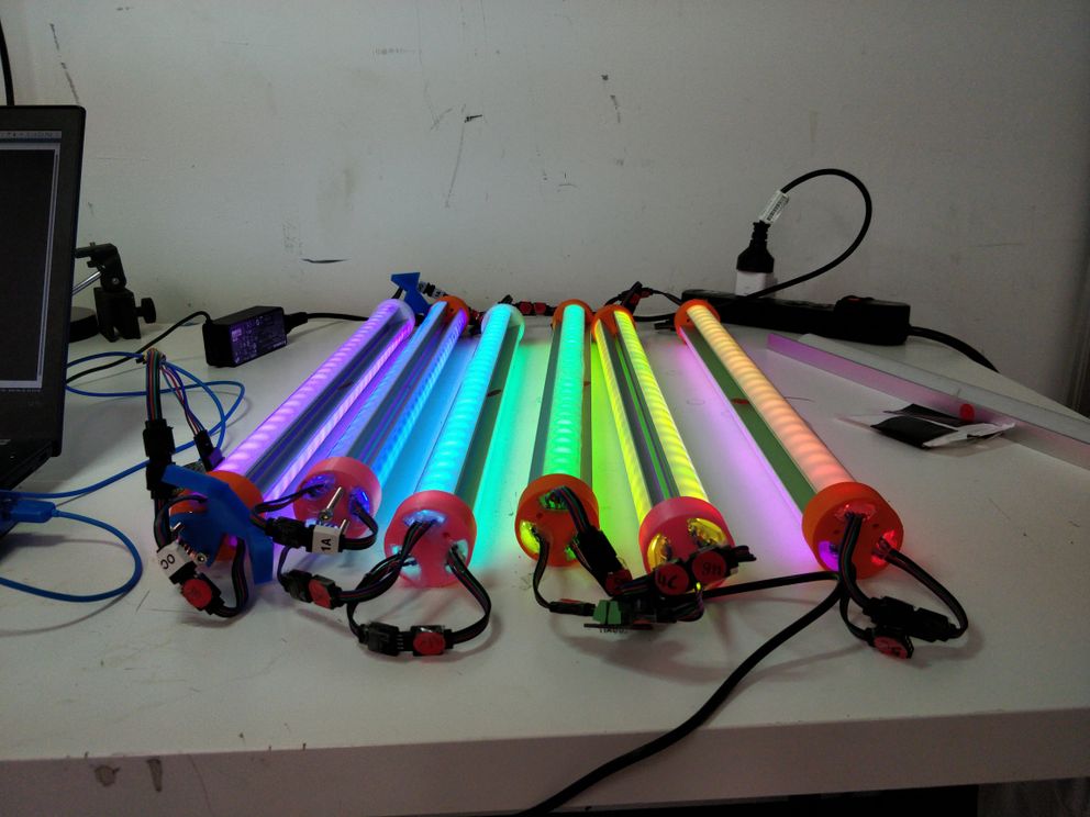
Then based on a tip from Piet, I sprayed the strips down with circuit board lacquer so they will be less likely to short (the aluminum is anodized, but scratch under the surface and you have a conductive metal touching the copper on the strips).
Then put on the diffusers and connected everything again, organized the “arms” by edge, even though it’s not yet in the shape of a tetrahedron. Goodness, I’ve never had a project be this clean and maybe even legit!
And all powered by this cute linux computer! 🐶
(And some other things, see complete bill of materials)
More updates!§
Here’s my new scene using 4-dimensional noise to determine colors! ([x, y, z, time] where time oscillates back and forth on each “beat” (TODO), slowly steps forward), got some help from Jack at Art~Hack.
Then added a button to change modes, except since I didn’t have an actual button I just tap the wires together. 😸
Yesterday, thanks to the other Jack, got the third print of the vertex structure, third time’s a charm! (actually this design needed changes, the 4th print looks good so far.)
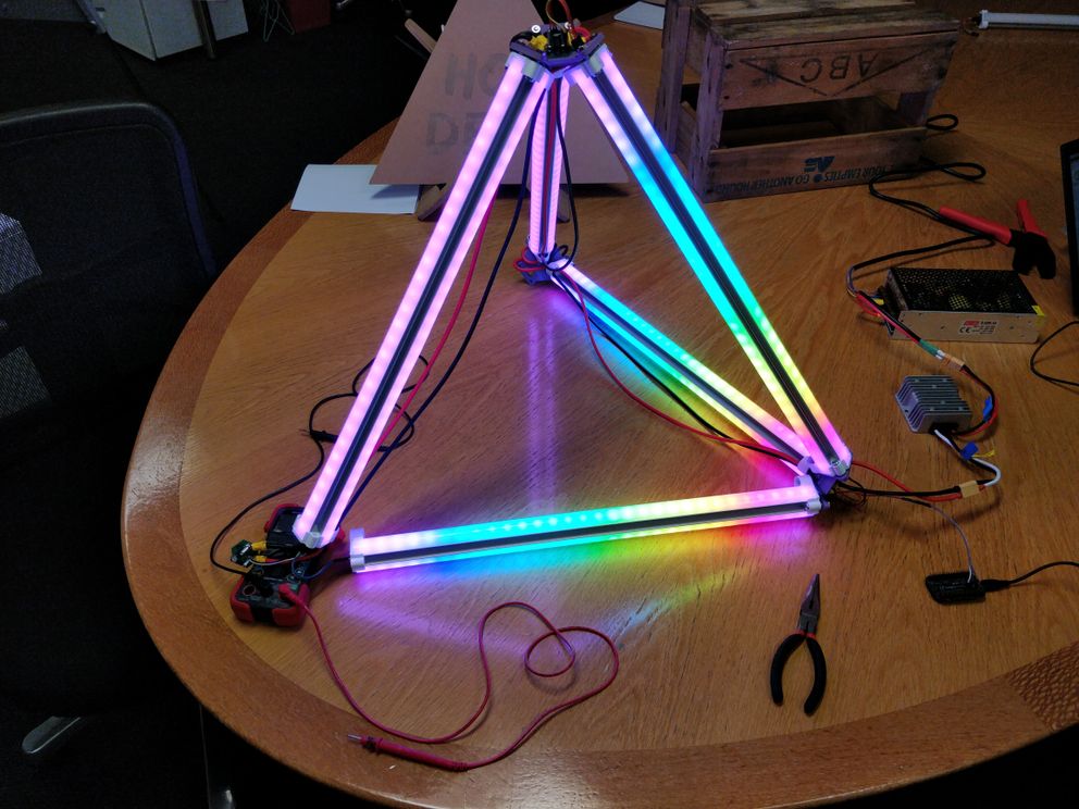
Mix helped me shape out the tetrahedron:
Then soldered some wires and used the 4th print to assemble a partial tetrahedron, it’s almost a thing!
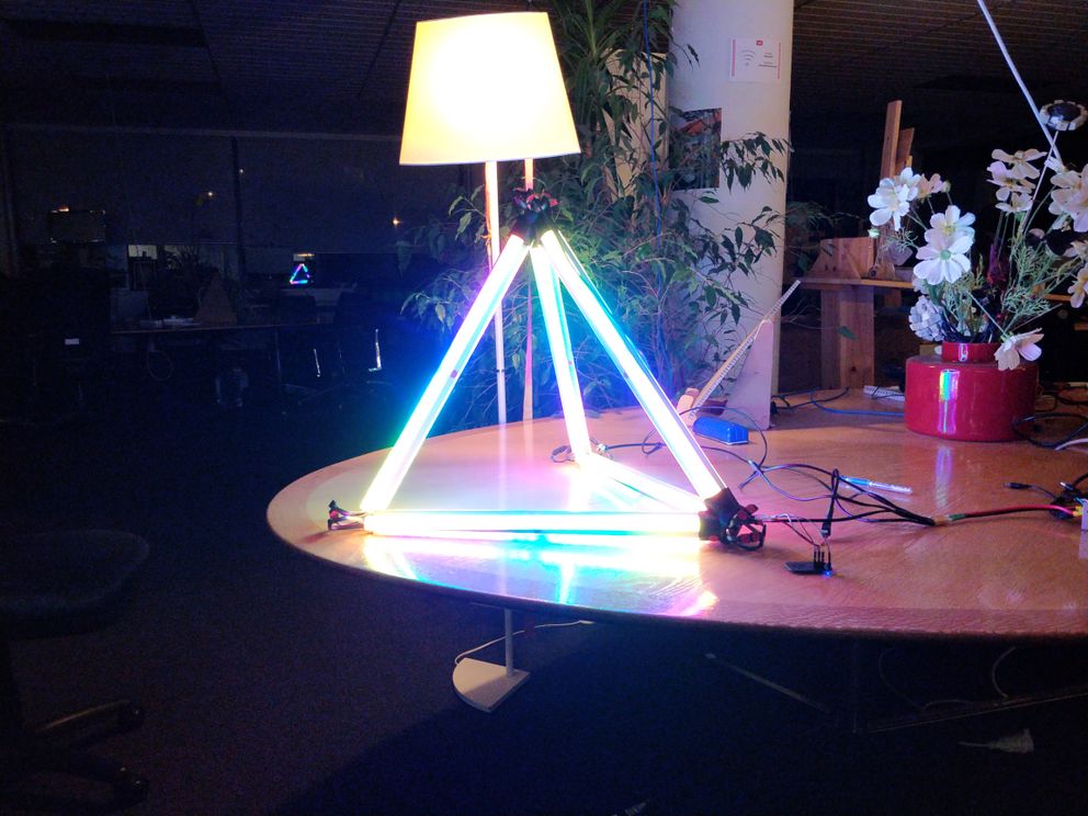
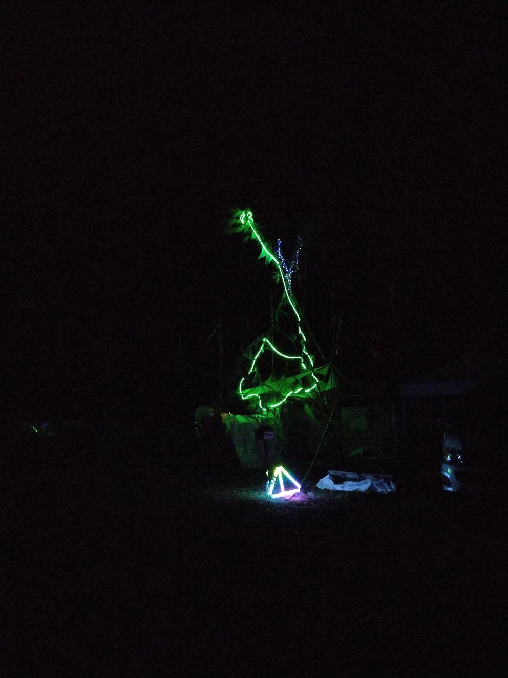
In motion!
I’m still in awe that any of this is working, it’s more beautiful than I deserve. 💖
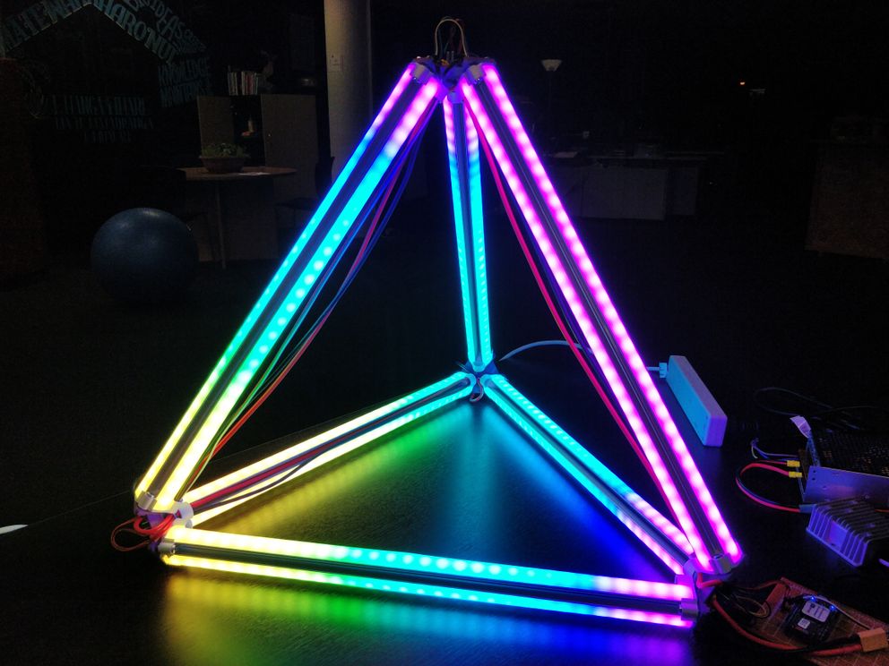
Demo§
Another splash of updates§
Another splash of updates! 🐋
I disassembled the tetrahedron and brought it with me to California. ☀ a bunch of wires soldered to the led strips broke when “unplugging” the led channels from the connector. So to make future dis-assembly and re-assembly less painful, I tried a new idea: what if the 3 led strips for a given edge connected to a edge part, and then 3 edge parts connected to a vertex part.
Here’s my first plug and socket design:
The “plug” design here was especially bad because a 3d printed part gets strength from horizontal, not vertical. So while I could connected the “plug” into the “socket”, given the lack of tolerance I pushed them tightly together and snap the “plug” broke off.
And then I realized, this is what threaded bolts 🔩 are for:
With this design, the edges are meant to be portable as units, so I discovered hot glue on both sides to prevent the wire connection from breaking and to keep out dust. 🌈
Then to bring to Burning Man, I found a bag and added 2 portable usb power packs, 🔋
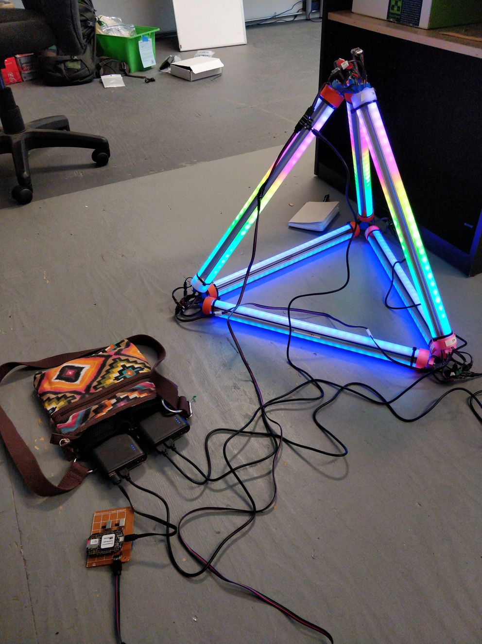
Added copious amounts of tape, to robustify the setup in danger of my lack of repair tooling,
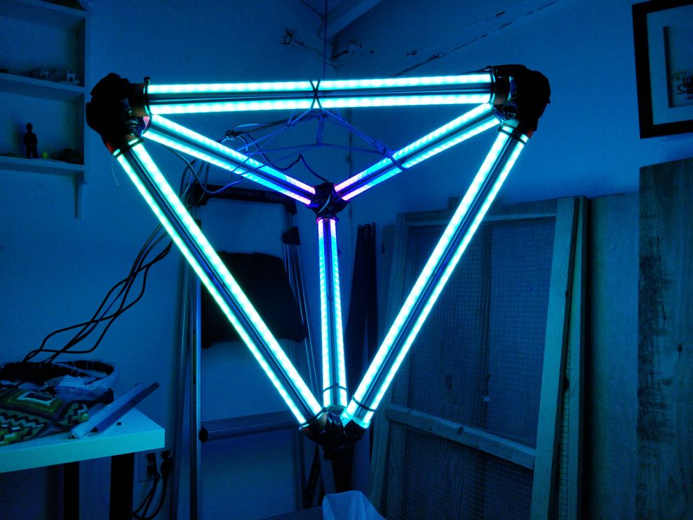
and hung the polyledra as a chandelier from rope 🐍
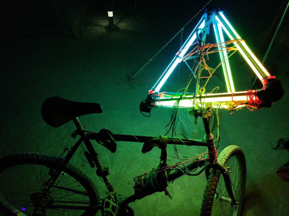
and later at the burn, tied to my bike. 🚲
This all landed swimmingly,
- nothing went wrong at the burn
- the batteries lasted all night, no problem
- one vertex part broke, but the tape kept everything together, as if nothing happened
- worked well
- hanging from rope at our home camp
- dancing with me and flowing around
- riding on a bike
Yay! 💃
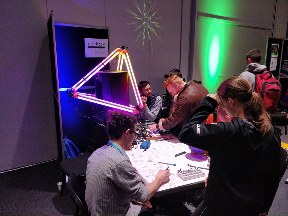
Then dis-assembled to bring back to New Zealand (during which time another two vertex parts broke), got replacements vertex parts printed at National Library Wellington, and re-assembled again for Art~Hack Spring Expo / Maker Faire Wellington.
Now to get ready for “I-Can’t-Believe-It’s-Not-Kiwiburn”:
- replace the wires with custom pcbs
- 1 per vertex
- 2 per edge (one on each side)
- fix the strength of the vertex part (by splitting the angle into a separate part which is printed sideways)
- make it waterproof (ready for the New Zealand outdoors)
- more frequent power injection (something goes wrong at higher power)
Rambles to share§
I figured that printing a custom PCB was highest priority, because the time between iterations could be up to a month, if I needed to have something printed overseas.
Okay, I played with KiCad before, I liked what it was doing but I didn’t like using the graphical interface, I wanted to think in terms of math (code). I was used to using OpenSCAD for my 3d modelling, I was used to writing code for physical objects, why not code for circuits?
I quickly realized KiCad used S-expressions to represent PCB components and boards. What if I wrote JavaScript which a read JavaScript config to generate a Kicad file?
So yeah: I made jseda & sexprs 😻
And made my first circuit with code:

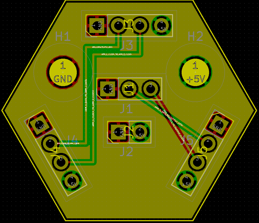
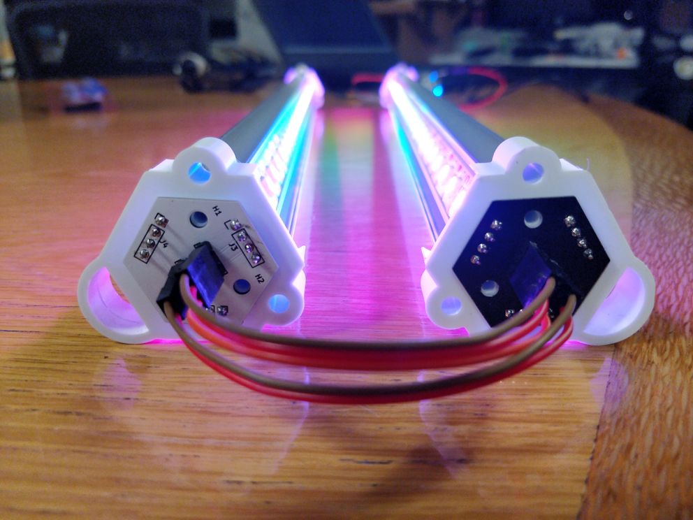
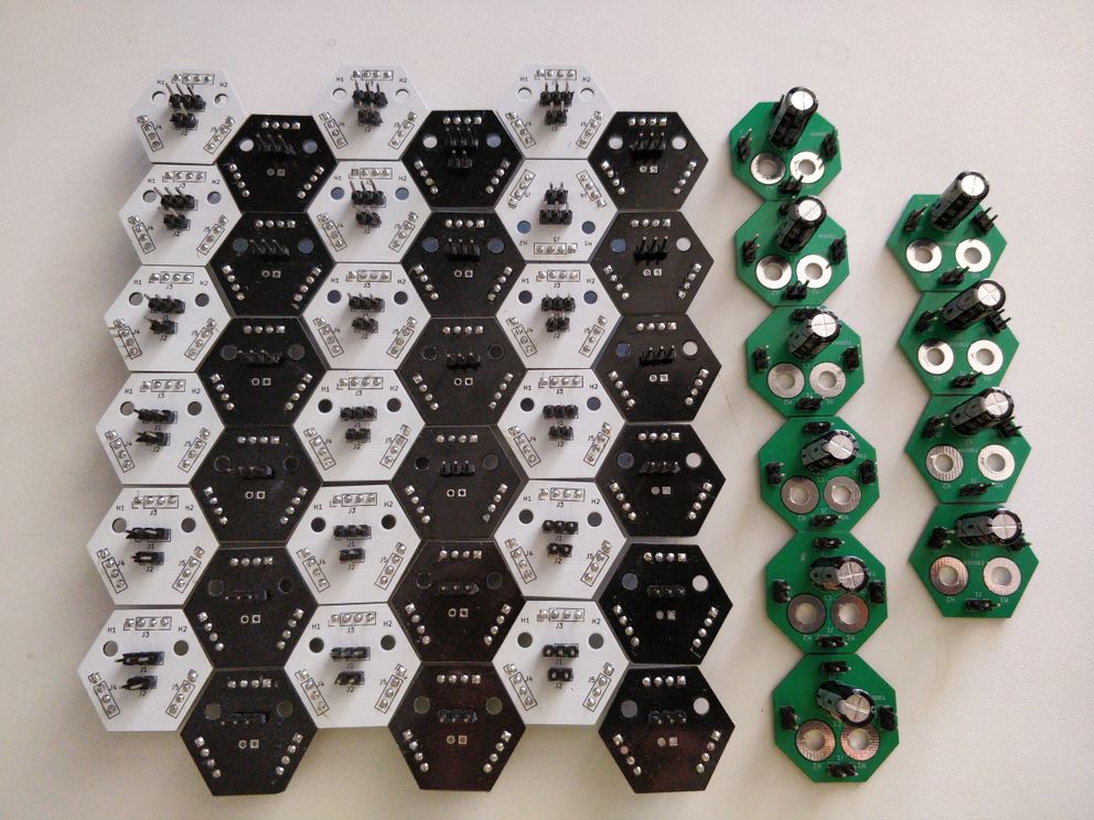
Which later became refined to the 4 circuits I need:
Edge, side a:
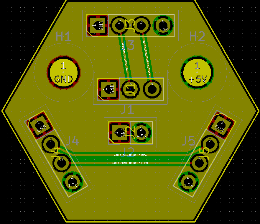
Edge, side b:
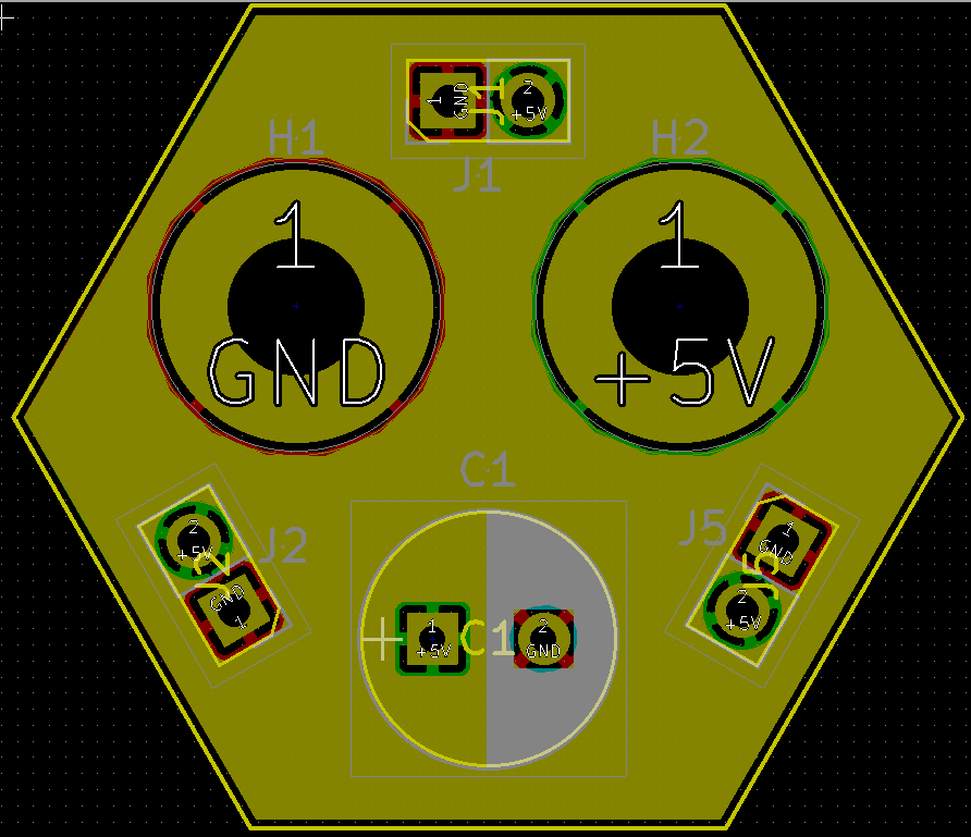
Tetrahedron vertex:
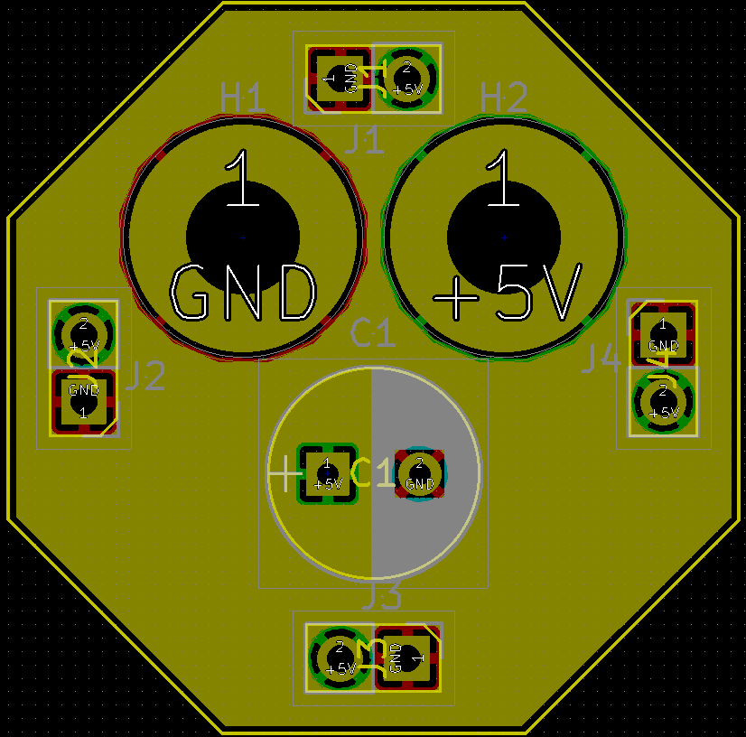
Octahedron vertex:
In this time I discovered that my whole time in Wellington (~4 years), during which time I lamented the lack of a local hackerspace, there has been a publicly-available Fab Lab: Fab Lab Wgtn, complete with 3D printers, laser cutters, multiple CNC machines, a PCB mill, and more. 😋
So I was hoping to prototype my circuits on the mill, even got help from Craig to use the mill. I ended up procrastinating on that front, so while the clock was ticking and the festivals approaching I decided to place my bets on my design and get my circuits made from Seeed Studios.
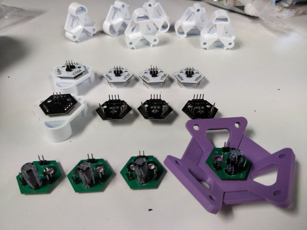
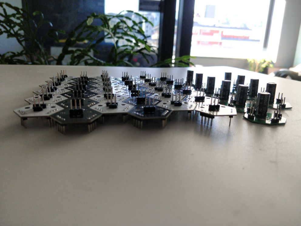
Today the circuits arrived, along with 3D prints I outsourced to be printed with PETG (stronger and more weatherproof than PLA)!
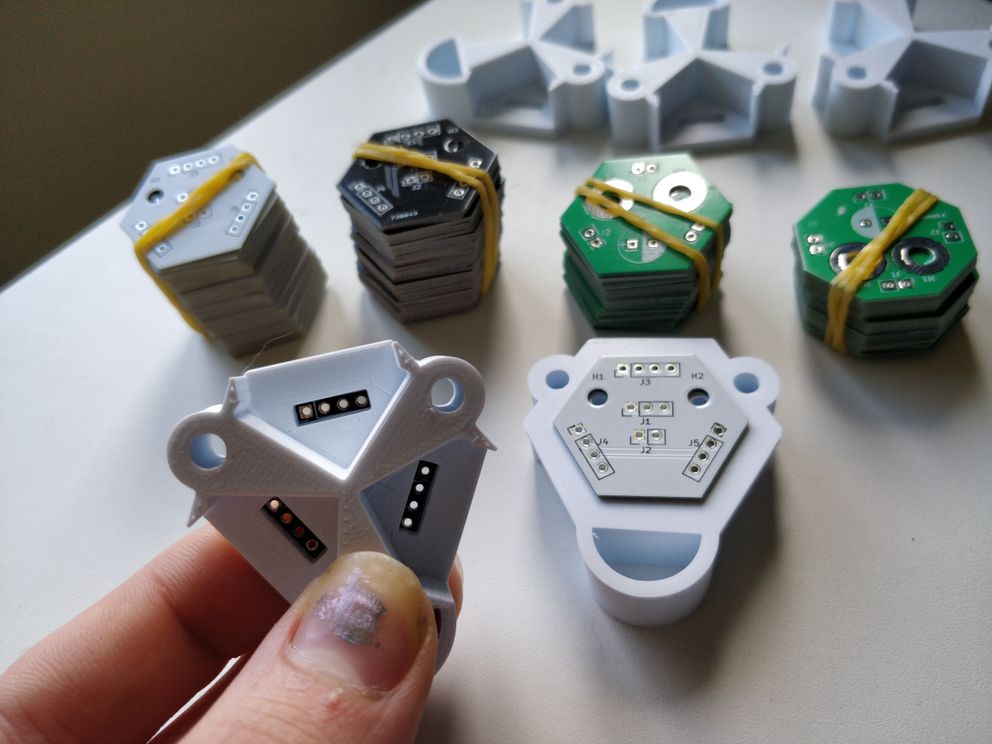
So far everything looks sweet as, I’m very excited. 😊 if everything checks out, I’ll be able to make a few more tetrahedrons, maybe an octahedron, with far better structural and electrical reliability than my current prototype, yay! 💃
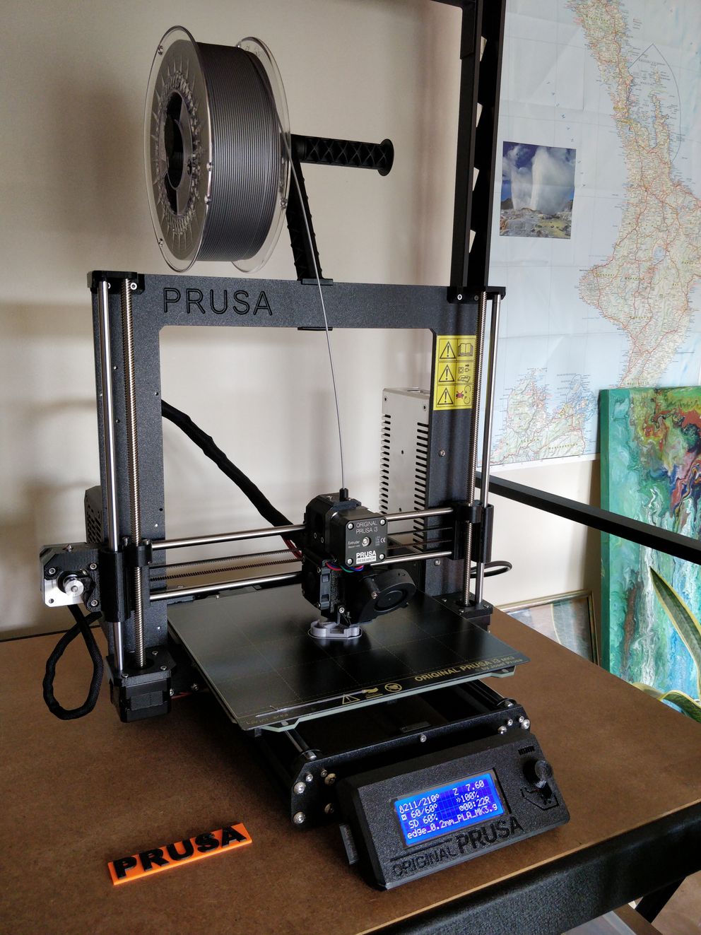
3D printers are happy§
Before I learned about Fab Lab Wgtn, I bought a 3D printer, which took a few months to arrive but finally did, it’s amaze. Back in the day I built a Prusa Mendel from a kit, which at the time I knew meant that my time and energy would be focused on the 3D printer itself. These days I wanted to focus on 3D printing, and Josef Prusa made a company selling their printers, so I bought a pre-assembled Prusa i3 MK3, I couldn’t be happier. 🔩
Meanwhile, I had a new idea to fix the vertex part, again keeping in the mind that the strength in a 3d printed part is printed layer by layer:
Instead of printing the angles of the vertex part as one, I made a separate part with the angle, to be printed on the side, maximizing strength. 💪
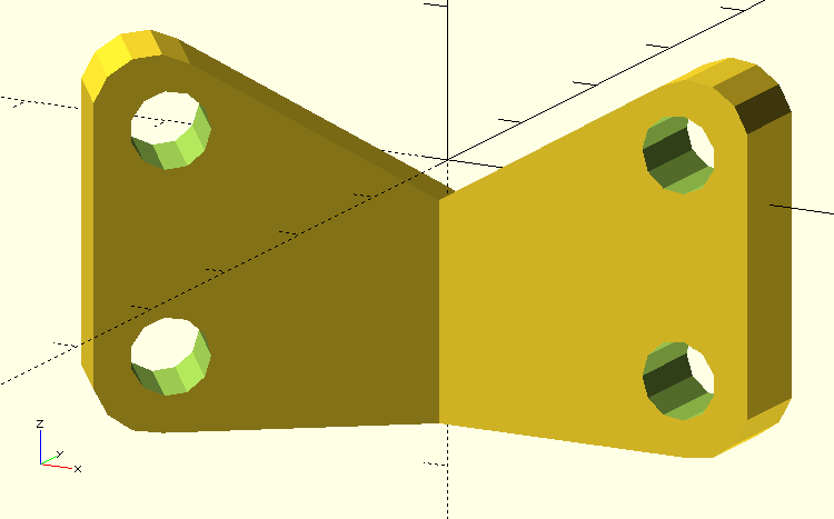
It worked, but meant I’d have another 3 sets of connectors to keep everything together. After some time exploring this new approach, I went back to the old approach and while not perfect I think it’s stronger than my last design and good enough for my purposes.
While I’ve been printing away, I ended up with PLA prototypes, wondering what to do with them. PLA is technically compostable and recyclable, but in practice you need a industrial composter (which is not available here in Wellington) and most recycling systems don’t accept PLA. Despite this reality, PLA is commonly used by your eco-friendly cafes as “compostable” coffee lids. Anyways, I’ve started re-using my PLA prototypes to make party jewelry, which has been working really well because my 3D designs are very symmetric and have appealing features (like the edge connector can look like a few faces, depending on how you angle it).
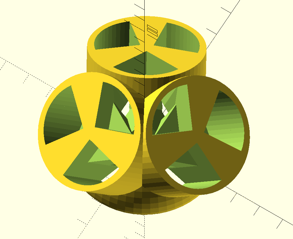
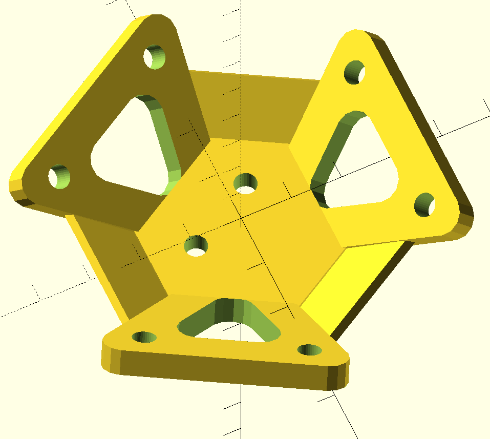
During this time, I also discovered an OpenSCAD library for polyhedra, which let me visualize the entire tetrahedron, with all the parts put together:
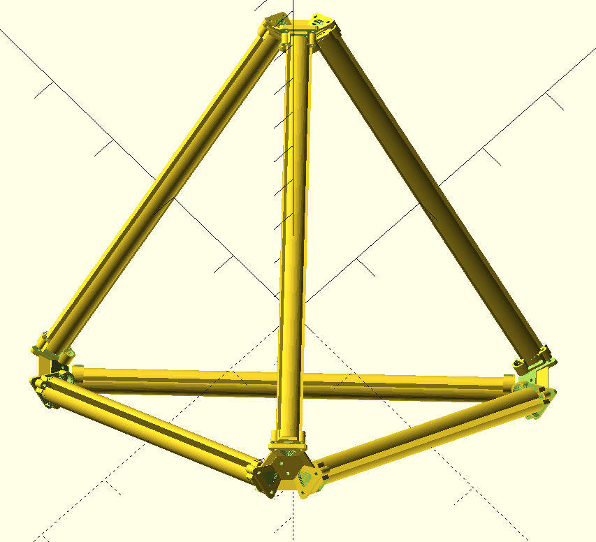
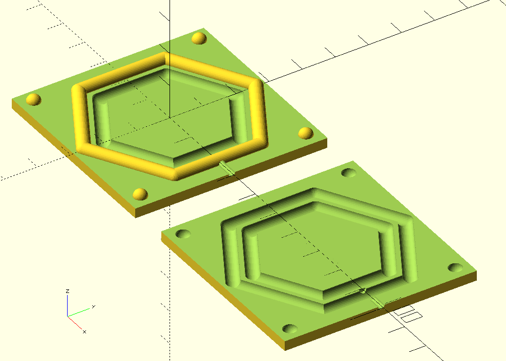
Oh, also I went down a side quest in the search for waterproofing, discovered the magic of o-rings and how they are used everywhere, I had no idea! I played around with making custom o-rings from making 3d models of molds to fill with rubber, Haven’t given this a hoon yet though.
Next iteration§
So far the next iteration of the tetrahedron is going well! 🌈
(Not pictured: all the time spent making a mess in the empty office while assembling and listening to drum & bass, or when I soldered things backwards and had to unsolder everything, or when twice I plugged the power plugs backwards (+5V into GND and vise versa) causing the wires to rapidly melt and burn))
Twisted§
Nowhere§
Double trouble§
“I-Can’t-Believe-It’s-Not-Kiwiburn”§
Scuttle camp§